During Operation Two Gears Are Said to Have Conjugate Motion if They Have: UPDATED
During Operation Two Gears Are Said to Have Conjugate Motion if They Have:
Introduction to Mechanisms
with
Susan Finger
Stephannie Behrens
Table of Contents
vii Gears
Gears are machine elements that transmit move by ways of successively engaging teeth. The gear teeth act like small levers.
vii.i Gear Classification
Gears may be classified according to the relative position of the axes of revolution. The axes may exist
- parallel,
- intersecting,
- neither parallel nor intersecting.
Here is a brief list of the common forms. We will discuss each in more particular afterwards.
- Gears for connecting parallel shafts
- Gears for connecting intersecting shafts
- Neither parallel nor intersecting shafts
Gears for connecting parallel shafts
- Spur gears
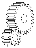
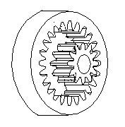
The left pair of gears makes external contact, and the correct pair of gears makes internal contact
- Parallel helical gears
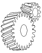
- Herringbone gears (or double-helical gears)

- Rack and pinion (The rack is similar a gear whose axis is at infinity.)

Gears for connecting intersecting shafts
- Straight bevel gears

- Spiral bevel gears
Neither parallel nor intersecting shafts
- Crossed-helical gears
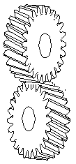
- Hypoid gears
- Worm and wormgear

7.ii Gear-Molar Action
7.2.1 Fundamental Law of Gear-Molar Action
Effigy 7-ii shows two mating gear teeth, in which
- Tooth profile ane drives molar profile 2 by acting at the instantaneous contact indicate K.
- N1N2 is the mutual normal of the two profiles.
- N1 is the human foot of the perpendicular from Oane to N1Northward2
- N2 is the human foot of the perpendicular from O2 to Northward1Due north2 .
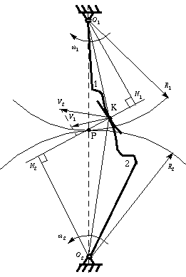
Figure vii-2 Two gearing tooth profiles
Although the two profiles accept different velocities V ane and V two at point K, their velocities along Due northoneN2 are equal in both magnitude and direction. Otherwise the two tooth profiles would separate from each other. Therefore, we take

or

We notice that the intersection of the tangency N1N2 and the line of centre OoneOii is indicate P, and

Thus, the human relationship between the angular velocities of the driving gear to the driven gear, or velocity ratio, of a pair of mating teeth is

Point P is very of import to the velocity ratio, and it is called the pitch point. Pitch point divides the line between the line of centers and its position decides the velocity ratio of the two teeth. The above expression is the primal law of gear-tooth action.
7.ii.2 Abiding Velocity Ratio
For a abiding velocity ratio, the position of P should remain unchanged. In this case, the motion transmission between ii gears is equivalent to the motility transmission betwixt two imagined slipless cylinders with radius Rane and R2 or diameter Di and D2 . Nosotros can get two circles whose centers are at Oi and Oii , and through pitch betoken P. These two circumvolve are termed pitch circles. The velocity ratio is equal to the inverse ratio of the diameters of pitch circles. This is the cardinal law of gear-molar action.
The fundamental law of gear-molar action may now as well be stated as follow (for gears with fixed eye distance) (Ham 58):
The common normal to the molar profiles at the point of contact must always pass through a fixed point (the pitch signal) on the line of centers (to become a constant velocity ration).
seven.two.3 Conjugate Profiles
To obtain the expected velocity ratio of two tooth profiles, the normal line of their profiles must laissez passer through the corresponding pitch point, which is decided past the velocity ratio. The two profiles which satisfy this requirement are chosen cohabit profiles. Sometimes, we simply termed the tooth profiles which satisfy the key constabulary of gear-tooth action the cohabit profiles.
Although many tooth shapes are possible for which a mating tooth could be designed to satisfy the key law, only 2 are in general use: the cycloidal and involute profiles. The involute has important advantages -- it is piece of cake to manufacture and the center distance between a pair of involute gears tin be varied without irresolute the velocity ratio. Thus close tolerances between shaft locations are not required when using the anfractuous profile. The most commonly used cohabit tooth curve is the involute bend (Erdman & Sandor 84).
seven.3 Involute Curve
The following examples are anfractuous spur gears. We use the word involute because the profile of gear teeth curves inward. Gears have many terminologies, parameters and principles. One of the of import concepts is the velocity ratio, which is the ratio of the rotary velocity of the commuter gear to that of the driven gears.
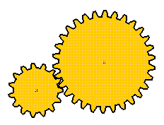
The SimDesign file for these gears is simdesign/gear15.30.sim. The number of teeth in these gears are fifteen and thirty, respectively. If the 15-molar gear is the driving gear and the xxx-teeth gear is the driven gear, their velocity ratio is 2.
Other examples of gears are in simdesign/gear10.30.sim and simdesign/gear20.thirty.sim
seven.3.one Generation of the Involute Curve
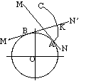
Figure 7-3 Involute curve
The bend most commonly used for gear-molar profiles is the anfractuous of a circumvolve. This involute curve is the path traced by a indicate on a line as the line rolls without slipping on the circumference of a circle. It may besides be defined as a path traced past the end of a string which is originally wrapped on a circle when the string is unwrapped from the circumvolve. The circle from which the involute is derived is called the base circle.
In Figure 7-3, allow line MN scroll in the counterclockwise direction on the circumference of a circle without slipping. When the line has reached the position K'North', its original point of tangent A has reached the position K, having traced the involute curve AK during the movement. As the move continues, the point A will trace the involute curve AKC.
7.three.two Properties of Involute Curves
- The altitude BK is equal to the arc AB, because link MN rolls without slipping on the circle.
- For any instant, the instantaneous center of the motion of the line is its signal of tangent with the circle.
Notation: We have not divers the term instantaneous center previously. The instantaneous center or instant heart is divers in 2 ways (Bradford & Guillet 43):- When two bodies accept planar relative move, the instant center is a betoken on one torso near which the other rotates at the instant considered.
- When two bodies have planar relative move, the instant center is the point at which the bodies are relatively at remainder at the instant considered.
- The normal at any point of an anfractuous is tangent to the base circle. Considering of the property (two) of the involute curve, the motion of the point that is tracing the involute is perpendicular to the line at whatsoever instant, and hence the curve traced will also be perpendicular to the line at whatever instant.
- There is no involute bend within the base circle.
7.four Terminology for Spur Gears
Figure 7-4 shows some of the terms for gears.
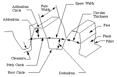
Effigy vii-4 Spur Gear
In the post-obit section, we define many of the terms used in the analysis of spur gears. Some of the terminology has been divers previously but we include them hither for completeness. (Run into (Ham 58) for more details.)
- Pitch surface : The surface of the imaginary rolling cylinder (cone, etc.) that the toothed gear may be considered to supercede.
- Pitch circle: A right section of the pitch surface.
- Addendum circle: A circle bounding the ends of the teeth, in a correct section of the gear.
- Root (or dedendum) circle: The circumvolve bounding the spaces between the teeth, in a right department of the gear.
- Addendum: The radial distance between the pitch circle and the annex circle.
- Dedendum: The radial distance betwixt the pitch circumvolve and the root circle.
- Clearance: The difference betwixt the dedendum of one gear and the addendum of the mating gear.
- Face of a tooth: That part of the tooth surface lying outside the pitch surface.
- Flank of a tooth: The part of the tooth surface lying inside the pitch surface.
- Circular thickness (too chosen the molar thickness) : The thickness of the tooth measured on the pitch circumvolve. It is the length of an arc and not the length of a straight line.
- Tooth infinite: The distance between adjacent teeth measured on the pitch circumvolve.
- Backlash: The deviation between the circle thickness of i gear and the tooth infinite of the mating gear.
- Circular pitch p: The width of a molar and a infinite, measured on the pitch circumvolve.
- Diametral pitch P: The number of teeth of a gear per inch of its pitch diameter. A toothed gear must have an integral number of teeth. The circular pitch, therefore, equals the pitch circumference divided past the number of teeth. The diametral pitch is, by definition, the number of teeth divided by the pitch diameter. That is,

and

Hence

where
- p = circular pitch
- P = diametral pitch
- N = number of teeth
- D = pitch diameter
That is, the product of the diametral pitch and the round pitch equals
 .
. - Module grand: Pitch diameter divided by number of teeth. The pitch bore is ordinarily specified in inches or millimeters; in the old case the module is the changed of diametral pitch.
- Fillet : The pocket-size radius that connects the contour of a molar to the root circle.
- Pinion: The smaller of any pair of mating gears. The larger of the pair is chosen only the gear.
- Velocity ratio: The ratio of the number of revolutions of the driving (or input) gear to the number of revolutions of the driven (or output) gear, in a unit of measurement of time.
- Pitch point: The bespeak of tangency of the pitch circles of a pair of mating gears.
- Common tangent: The line tangent to the pitch circumvolve at the pitch betoken.
- Line of action: A line normal to a pair of mating tooth profiles at their point of contact.
- Path of contact: The path traced by the contact signal of a pair of tooth profiles.
- Pressure angle
 : The bending between the common normal at the indicate of tooth contact and the common tangent to the pitch circles. It is also the bending between the line of action and the mutual tangent.
 - Base circle :An imaginary circle used in involute gearing to generate the involutes that form the tooth profiles.
Table vii-i lists the standard tooth system for spur gears. (Shigley & Uicker lxxx)
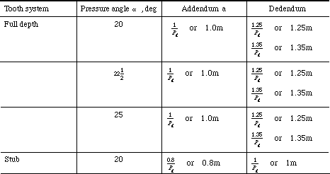
Table 7-1 Standard tooth systems for spur gears
Table 7-ii lists the normally used diametral pitches.
| Coarse pitch | 2 | ii.25 | 2.5 | 3 | iv | 6 | viii | 10 | 12 | 16 |
| Fine pitch | 20 | 24 | 32 | 40 | 48 | 64 | 96 | 120 | 150 | 200 |
Table 7-2 Commonly used diametral pitches
Instead of using the theoretical pitch circumvolve as an index of tooth size, the base of operations circle, which is a more key circle, can be used. The outcome is called the base pitch pb , and it is related to the round pitch p by the equation

7.5 Condition for Correct Meshing
Figure 7-five shows two meshing gears contacting at point M1 and Mii .
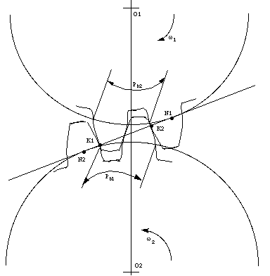
Effigy 7-5 2 meshing gears
To go a correct meshing, the distance of Grand1Chiliadtwo on gear 1 should be the same every bit the altitude of KaneKtwo on gear ii. Equally One thousandiThousand2 on both gears are equal to the base of operations pitch of their gears, respectively. Hence

Since

and

Thus

To satisfy the to a higher place equation, the pair of meshing gears must satisfy the following condition:

7.6 Ordinary Gear Trains
Gear trains consist of two or more gears for the purpose of transmitting motion from i axis to some other. Ordinary gear trains have axes, relative to the frame, for all gears comprising the train. Figure 7-6a shows a elementary ordinary railroad train in which there is just one gear for each axis. In Effigy 7-6b a compound ordinary train is seen to exist one in which 2 or more gears may rotate well-nigh a unmarried axis.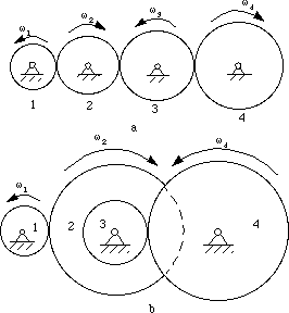
Figure 7-6 Ordinary gear trains
7.six.1 Velocity Ratio
Nosotros know that the velocity ratio of a pair of gears is the inverse proportion of the diameters of their pitch circle, and the bore of the pitch circumvolve equals to the number of teeth divided by the diametral pitch. Also, we know that it is necessary for the to mating gears to have the same diametral pitch so that to satisfy the condition of correct meshing. Thus, nosotros infer that the velocity ratio of a pair of gears is the changed ratio of their number of teeth.
For the ordinary gear trains in Figure vii-6a, we have

These equations can be combined to give the velocity ratio of the first gear in the train to the last gear:

Note:
- The tooth number in the numerator are those of the driven gears, and the tooth numbers in the denominator vest to the commuter gears.
- Gear ii and 3 both drive and are, in plow, driven. Thus, they are called idler gears. Since their tooth numbers cancel, idler gears do not touch the magnitude of the input-output ratio, merely they practise change the directions of rotation. Annotation the directional arrows in the figure. Idler gears can also institute a saving of space and money (If gear 1 and four meshes directly beyond a long center distance, their pitch circle will be much larger.)
- There are two ways to determine the direction of the rotary management. The offset manner is to characterization arrows for each gear equally in Figure 7-half-dozen. The second mode is to multiple mth ability of "-1" to the general velocity ratio. Where 1000 is the number of pairs of external contact gears (internal contact gear pairs exercise not change the rotary management). However, the 2nd method cannot be applied to the spatial gear trains.
Thus, it is not difficult to become the velocity ratio of the gear train in Figure 7-6b:

7.7 Planetary gear trains
Planetary gear trains, likewise referred to as epicyclic gear trains, are those in which one or more gears orbit nearly the central axis of the train. Thus, they differ from an ordinary train by having a moving centrality or axes. Effigy 7-eight shows a basic arrangement that is functional by itself or when used as a function of a more circuitous organisation. Gear 1 is called a sun gear , gear 2 is a planet, link H is an arm, or planet carrier.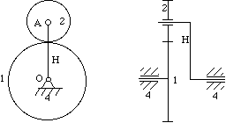
Figure 7-eight Planetary gear trains

Figure seven-seven Planetary gears modeled using SimDesign
The SimDesign file is simdesign/gear.planet.sim. Since the sun gear (the largest gear) is fixed, the DOF of the in a higher place machinery is 1. When you pull the arm or the planet, the mechanism has a definite motion. If the sun gear isn't frozen, the relative motion is hard to control.
seven.seven.1 Velocity Ratio
To make up one's mind the velocity ratio of the planetary gear trains is slightly more complex an analysis than that required for ordinary gear trains. We will follow the process:
- Invert the planetary gear train mechanism past imagining the application a rotary motion with an angular velocity of
 H to the mechanism. Let's analyse the motion before and after the inversion with Tabular array 7-three:
Table 7-3 Inversion of planetary gear trains.
Notation: H is the rotary velocity of gear i in the imagined mechanism.
 Discover that in the imagined machinery, the arm H is stationary and functions as a frame. No centrality of gear moves any more than. Hence, the imagined mechanism is an ordinary gear train.
- Apply the equation of velocity ratio of the ordinary gear trains to the imagined machinery. We become

or

seven.7.2 Instance
Accept the planetary gearing railroad train in Figure 7-viii as an example. Suppose Northone = 36, Nii = eighteen,  1 = 0,
  2 = 30. What is the value of
  N?
N?
With the application of the velocity ratio equation for the planetary gearing trains, we accept the following equation:

From the equation and the given weather, nosotros can get the reply:  N = ten.
![]()
Table of Contents
Complete Table of Contents- i Physical Principles
- 2 Mechanisms and Unproblematic Machines
- 3 More on Machines and Mechanisms
- 4 Basic Kinematics of Constrained Rigid Bodies
- 5 Planar Linkages
- half-dozen Cams
- vii Gears
- 7.ane Gear Classification
- 7.two Gear-Molar Activity
- 7.2.i Fundamental Law of Gear-Tooth Activeness
- seven.two.two Abiding Velocity Ratio
- 7.2.3 Cohabit Profiles
- 7.3 Anfractuous Curve
- 7.three.1 Generation of the Involute Curve
- 7.3.two Backdrop of Involute Curves
- 7.iv Terminology for Spur Gears
- seven.five Condition for Correct Meshing
- 7.vi Ordinary Gear Trains
- seven.6.1 Velocity Ratio
- 7.7 Planetary gear trains
- 7.7.i Velocity Ratio
- seven.7.two Example
- viii Other Mechanisms
- Index
- References
![]()


sfinger@ri.cmu.edu
DOWNLOAD HERE
During Operation Two Gears Are Said to Have Conjugate Motion if They Have: UPDATED
Posted by: kevinretontook.blogspot.com

Comments
Post a Comment